 English
  English
 Views: 5 Author: Site Editor Publish Time: 2021-11-18 Origin: Site
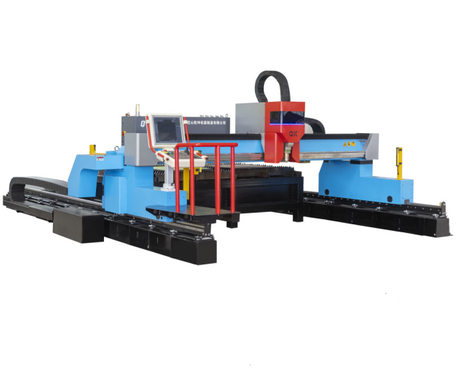
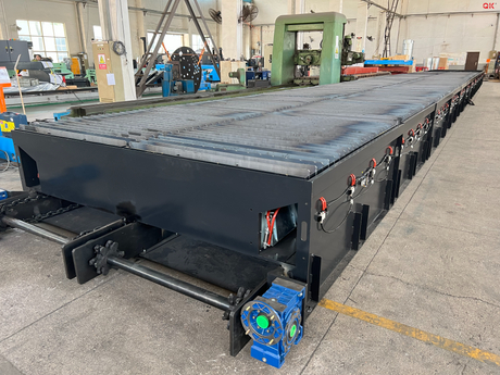
Plasma is a height ionospheric that is heated to a high temperature, transmitting arc power to the workpiece, high thermal melting to blow away the workpiece, thereby forming a plasma arc cutting operation.Plasma cutting machineIt is a processing apparatus for removing the molten metal to form a gap using the momentum of the high-speed plasma, which is widely used due to the smooth and thermal deformation of the cutting surface. The existing ion cutting machine includes a bed and a reservoir, a cutting device is provided above the bed; the cutting device includes a support frame, a crossbar, and a cutting head; the support frame is disposed at both ends of the crossbar; cutting head is mounted on the crossbar On; the gas supply device is connected to the cutting head; the bed surface is provided with a water tank; and there is a plurality of fences in the water tank; there is a slider on both sides of the bed; two ends of the slider are provided with a stroke switch. . The cutting head is cut back and forth in the bed, so the bed is large, the cutting area is large, the cutting slag falls into the tank, easy to collect the slag, small pollution, high efficiency. The prior art solution exists in a disadvantage: during the process of machining the L-shaped plate, both sides of the L-shaped plate need to be cut, the bed is a planar structure, which is not conducive to the fixation of the L-shaped plate.

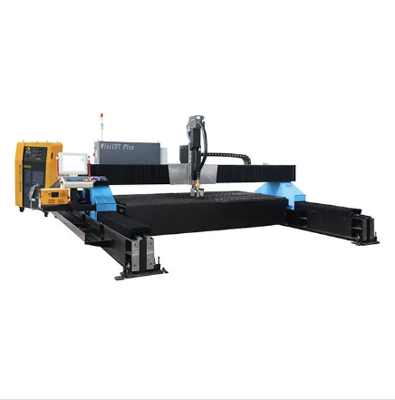
In response to the shortcomings of existing technologies, technicians provide a kind ofPlasma cutting machineThe L-shaped plate is fixed by a support plate provided with a card slot, so that one side card of the L-shaped plate is placed on the support plate in the card slot, and the other side is placed on the support plate, which is convenient for cutting. Further, a clamp connection through the rotating device and the air pressure cylinder is further clamped and lifted, and after rotating by the rotating device, the cutting of the two L-plates is achieved. The plasma cutting machine is achieved by a plasma cutting machine, including a rack and a controller, a cutting device above the rack, characterized in that the rack is provided with a support with the rack vertical. The plate, the support plate is located on both sides of the cutting device, and a card slot disposed on the support plate and the opening towards the cutting device side; the support plate is remote from the cutting device, and the cylinder is provided on the side of the cutting device; the clamping groove and the cylinder are located on the same straight line. The cylinder is slidable with the rack and slides in the connection direction of the cylinder and the card slot; the output shaft of the air pressure cylinder is disposed vertically, and is connected to the jig toward the support plate side; the clamp is provided between the output shaft of the air pressure cylinder. There is a rotating device. The card slot that is vertically disposed on the support plate can be caught on one side of the L-plate plate into the card slot, and the other side can be placed automatically on the support plate to facilitate cutting the device. After the processing of one side of the L-shaped plate is completed, the sliding device drives the clamp to fix the L-shaped plate, and then the cylinder is extended, and the L-shaped plate is moved upward, and from the card slot. Then the rotating device rotates the L-shaped plate, and the cylinder shrinks the cutting side of the L-plate plate into the clamping slot, at which time the clamping groove is horizontally supported. The rotating device includes a mounting plate that is fixedly coupled to the cylinder output shaft, and a rotary cylinder having a fixture is fixedly coupled to the clamp. The rotating device is configured to rotate the cylinder, which can rotate the clamp, thereby realizing the rotation of the L-shaped plate, changing its cutting plane.
In summary, the abovePlasma cutting machineThe beneficial technical effect is as follows:
1. The card slot vertically disposed on the support plate facilitates the fixed and supporting the L-shaped plate, and the active positioning plate is set at the card slot position, adjust the slot size of the card slot to accommodate different specifications and sizes;
2, the sliding device and the cylinder on both sides of the support plate cooperate with the rotating device, drive the clamp clamping the L-shaped plate and rotate, change the contact surface of the L-shaped plate and the clamping tank, and then cut the two sides of the L-plate plate;
3, the rotating device is fixed at right angles to the L-shaped plate to ensure that the side surface of the L-shaped plate rotation can match the card slot; at the same time, the connection position of the rotating device uses a cross-shaped projection and a clamping device and a cross groove phase. In cooperation, it can improve the connection stability of both.
Kunshan Qiankun Machinery Manufacturing Co., Ltd.
After more than ten years of continuous efforts, we have delivered more than one thousand sets of various cutting machines, which create value for customers all over the world. Every year, nearly half of the machines are exported to Southeast Asia and Europe.
SOCIAL ATTENTION

Copyright © 2021
Kunshan Qiankun Machinery Manufacturing Co., Ltd.
Partners:Leading foreign trade station
record number:Su ICP No. 2021003781